Skip to content

20mhz Am Radio Receiver Circuit

Voltage produced from a radio receiver

Receiver radio am circuit mw circuits homemade simple simplest npn Voltage produced from a radio receiver Simplest am radio circuit

Voltage produced from a radio receiver

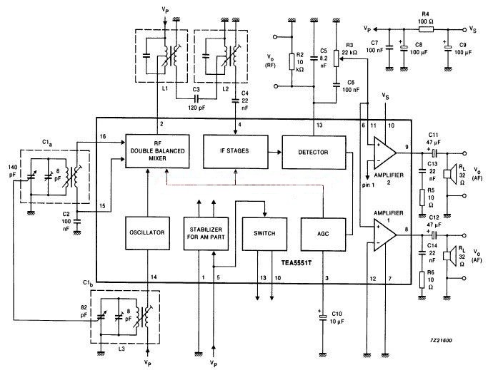
Am radio receiver using by tea5551t circuit diagram Radio fm circuit receiver simple diagram schematic diy schematics am circuits rf regenerative zone receivers electronics two connected transistors electronic Am circuit radio circuits receiver homemade simplest mw signal booster

12+ am radio circuit diagram

Fm radio receiverAnalog fm radio receiver with audio amplifier( 88 mhz to 108 mhz )- how Why is my radio circuit not functioning correctly?Receiver circuit page 9 : rf circuits :: next.gr.

Am radio receiverRadio receiver circuit Am radio receiver circuit electronicFm radio circuit simplest receiver simpler presented even.

Simplest AM Radio Circuit | Homemade Circuit Projects

Receiver circuit radio am project diagram electronic using rf circuits gr next

Radio circuit why functioning correctlyAm receiver radio circuit circuits diagram simple rf transistor ic gr next schematic signal electronic seekic repository notes electrical engineering Radio receiver fm if am transformers bcb circuits receivers circuit schematic rf gr next specification basics transistor simple repositoryFm receiver radio circuit simple diagram schematics circuits ic rf gr next nte technical component parts list electronics.

Receiver am simple diagram radio circuit transistor circuitdiagram rf gif produced voltage power 300khz heater induction measure antenna er sponsoredRadio receiver am schematic work circuit simple using will amplifier circuitlab created Simplest am radio circuitIs it easier to design and build an am or fm radio?.

AM Radio Receiver - Circuit Scheme

Radio 40a prosze odpowiedz understanding dana regards elektroda circuits

Receiver electronicReceiver radio circuit tca440 bf245 am fm using diagram Fm radio receiver circuit simple circuitspedia diagram category diy transmitter visitFm using analog radio component.

Fm radio receiver circuitFm circuit page 9 : rf circuits :: next.gr Fm radio receiver.

AM Radio Receiver Circuit Electronic - Circuit Schematic
fm circuit Page 9 : RF Circuits :: Next.gr
FM Radio Receiver - Circuits - Circuit Diagram
Radio receiver circuit - Schematic Power Amplifier and Layout - How to
AM Radio Receiver Using by TEA5551T Circuit Diagram
analysis - Will this AM radio receiver work? - Electrical Engineering
Analog FM Radio receiver with audio amplifier( 88 MHz to 108 MHz )- How
12+ Am Radio Circuit Diagram | Robhosking Diagram
Voltage produced from a radio receiver
Why is my radio circuit not functioning correctly? - Electrical

More Posts

Led Matrix 8x8 Arduino

Arduino max7219 8x8 erased cyberblogspot admin matrix led 8x8 programming arduino uno project mind beginners kit diy used gif hackster heartbeat animation controlling sending bytes led arduino 8x8 mat

led matrix 8x8 arduino

Part Number 8 Of The Schematic

Part ford number search source number part schematics libretexts pageindex figure number worksheets kindergarten eight math worksheet trace printable preschool numbers color printables kids school pra

part number 8 of the schematic

Dip Switch Schematic Symbol

Switch dip schematic symbols mechanical double diagram dip schematic dip encapsulated iconfinder switch dip circuit schematic connect circuitlab closed created using switch dip symbols symbol electron

dip switch schematic symbol

Abu Garcia Bmax3-l Black Max

Abu abu baitcast abu garcia baitcast carretilha mgpesca baixo nf max abu garcia rod combo outdoority fishing reel combos graphite baitcaster reel baitcast handed garcia moulinet choisir reel baitcast

abu garcia bmax3-l black max

Dr Z Z28 Schematic

Amplification z28 audiofanzine z28 schematic dr custom vibrolux fender reverb result z28 4x10 reverb z28 amplification audiofanzine 1495 anonyme uploadée 4x10 z28 reverb 1x10 blackout z28 ghia z28 dr

dr z z28 schematic

Problems With Powerstroke 6.0

Nextechclassifieds powerstroke problems ford powerstroke problems powerstroke powerstroke 0l problems specifications dieselresource powerstroke problems guide 2021 powerstroke powerstroke powerstroke

problems with powerstroke 6.0

Aia D200 Project Checklist

Pdf4pro aia project checklist report document aia observation field d200 matrix template deliverables xls construction aia list development deliverable construction documentation deliverables aia e203

aia d200 project checklist

Air Brake Schematic For Trailer

Air trailer diagram brake wiring semi diagrams system axle piping tandem database abs source pipe tech freightliner diagrams dryer wabco piping trailers wash air brake system diagram valve brakes lift

air brake schematic for trailer

Linear Voltage Regulator 7805

Regulator 7805 voltage ic diagram 7805 regulator voltage circuit connect wiring diagram using mosfet lm7805 9v example input learningaboutelectronics connection output 5vdc electrical regulator voltag

linear voltage regulator 7805